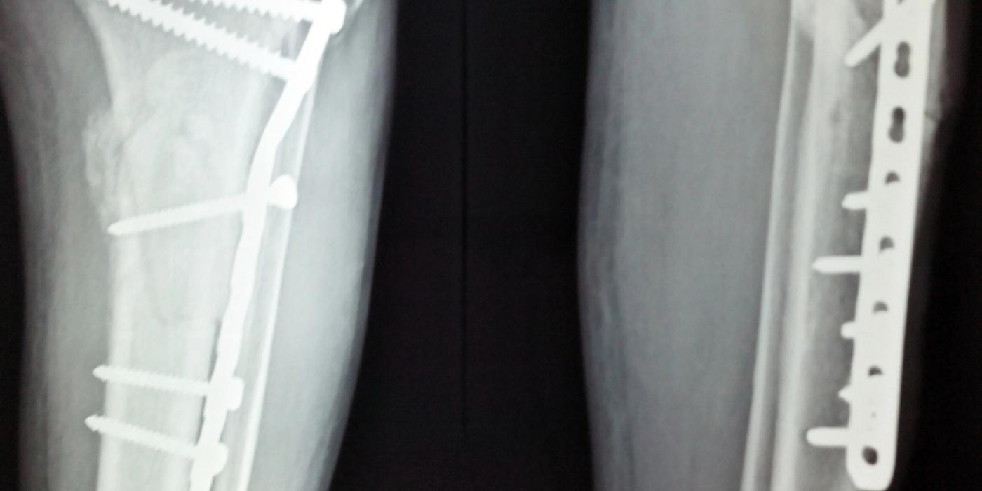
Lag screw fixation is a technique of internal fixation in which a screw compresses two fracture fragments together, generating interfragmentary compression and therefore absolute stability. The screw must grip only the far fragment — either because a glide hole is drilled in the near cortex (lag by technique) or because the screw is partially threaded (lag by design) — so that tightening the head draws the far fragment towards the near one. It is the workhorse method for simple oblique and spiral fracture patterns and for articular fragments, and in diaphyseal bone it is almost always protected by a neutralisation plate.
Why does interfragmentary compression matter?
Compression across a fracture abolishes interfragmentary movement. As the AO Surgery Reference states, "absolute fracture stability, which is defined as the complete abolition of interfragmentary movement, is achieved by interfragmentary compression and results in direct bone healing in simple fracture configurations". Direct (primary) cortical healing occurs by osteonal cutting cones crossing the fracture without callus, which is why an anatomically reduced, lagged fracture should show no callus on follow-up radiographs — visible callus after absolute-stability fixation suggests unwanted motion at the fracture site. This is the practical application of Perren's strain theory (classic AO teaching): rigid compression keeps strain at the fracture gap low enough for bone to form directly. The corollary matters just as much at interview: absolute stability is unforgiving. It demands anatomical reduction of a simple pattern; applied to comminution it produces gaps, high strain and non-union.
What is the difference between lag by technique and lag by design?
Both achieve the same mechanical end: the screw thread purchases only the far fragment, and compression is generated between the undersurface of the screw head on the near fragment and the threads in the far fragment.
| Lag by technique | Lag by design | |
|---|---|---|
| Screw | Fully threaded cortical screw | Partially threaded (shaft) screw |
| How lag is achieved | Glide hole over-drilled in the near cortex to the outer thread diameter, so "the thread gets no purchase" in the near fragment | The smooth shank slides in the near fragment; only the distal threads engage, and all threads must lie beyond the fracture line |
| Typical use | Diaphyseal cortical bone (e.g. 3.5 mm cortical screw) | Metaphyseal and cancellous bone (e.g. 4.0 mm cancellous or 6.5 mm cancellous screws) |
| Key failure mode | Forgetting the glide hole — the screw grips both cortices and holds the gap open instead of compressing it | Threads crossing the fracture line, which prevents compression |
If the glide hole is omitted, the screw threads engage both fragments and the fracture is fixed distracted — a positional screw, not a lag screw. This distinction is a standard interview probe.
How do you insert a lag screw step by step?
For a fully threaded 3.5 mm cortical screw in diaphyseal bone (the standard viva answer), after anatomical reduction and provisional clamp fixation:
- Glide hole: drill the near cortex with a 3.5 mm drill (equal to the outer thread diameter) so the thread cannot purchase.
- Insert a drill sleeve into the glide hole to centre the next drill.
- Pilot (thread) hole: drill the far cortex with a 2.5 mm drill (equal to the core diameter).
- Countersink the near cortex in diaphyseal bone to increase the contact area under the screw head and reduce the risk of stress-riser fracture. Avoid countersinking thin metaphyseal cortex, as it "removes support for the screw head"; a washer may be used instead.
- Measure with a depth gauge, angling to read the longest length so the thread fully clears the far cortex.
- Tap the far cortex to cut the thread (unless using a self-tapping screw — classic teaching cautions against self-tapping screws for lag fixation because, if re-angled, they "cut a new path and destroy already cut thread").
- Insert and tighten the screw, watching the fracture line close under compression with two-finger tightness; avoid stripping, especially in osteoporotic bone.
Orientation is critical: the screw should be inserted perpendicular to the fracture plane. Biomechanical work by Johner et al (1983, cited in Wheeless' Textbook of Orthopaedics) showed that fracture sliding occurs when compression is applied more than about 20 degrees off the perpendicular to the fracture surface — an obliquely inserted screw shears and displaces the reduction as it is tightened. Where a single screw must resist both compression and axial load, the classic compromise is to place it bisecting the angle between the perpendicular to the fracture and the perpendicular to the long axis of the bone; with multiple screws in a spiral fracture, each follows the helical fracture plane in a slightly different direction.
When is lag screw fixation appropriate — and when is it not?
- Simple oblique or spiral fractures where anatomical reduction is achievable. AO teaching is that lag screws alone suffice only when the fracture length is at least two (ideally two to three) times the diameter of the bone at that level, allowing a minimum of two screws; shorter fracture lines need a single lag screw plus a protection plate.
- Articular fractures — lag fixation is the default for displaced intra-articular fragments (e.g. malleolar, condylar, capitellar fragments), because congruent joint surfaces demand anatomical reduction and absolute stability.
- Not appropriate for multifragmentary or comminuted fractures (compression cannot be generated across comminution and devascularises fragments), for most osteoporotic diaphyseal fractures, or wherever relative-stability bridging constructs (bridge plate, intramedullary nail) better respect the biology. Choosing lag fixation for a comminuted fracture is a recognised cause of non-union and implant failure.
When do you combine a lag screw with a neutralisation plate?
A lag screw resists tension along its own axis but is weak against torsion, bending and shear. In diaphyseal bone these forces are large, so the lag screw is protected: as the AO Surgery Reference puts it, "in order to protect the primary lag screw fixation, a perfectly contoured plate is applied adjacent to the screw head without axial compression (all screws in the neutral position)" — the plate "then acts as a neutralization (protection) plate and axial compression should not be applied". Good-practice points:
- The lag screw provides the compression; the plate provides none. All plate screws go in neutral, not eccentric, positions.
- In the forearm, "in addition to any lag screw, three bicortical plate screws are required in each main fracture fragment due to the high torsional stresses" (AO Surgery Reference).
- Where geometry allows, the lag screw may be placed through a plate hole rather than as an independent screw.
- The classic UK exemplar is the Weber B lateral malleolus: independent or through-plate lag screw plus a one-third tubular neutralisation plate. This sits within BOAST 12 (Ankle Fractures, Aug 2016), which states that "surgery should aim to achieve reduction and stabilisation of the ankle mortise. The syndesmosis should then be assessed and stabilised if unstable", with intraoperative imaging to confirm reduction and fixation; postoperatively "most patients should be allowed to bear weight as tolerated" unless there is a specific contraindication.
What are the common pitfalls and complications?
- Omitting the glide hole — fixing the fracture in distraction (positional, not lag, effect).
- Threads of a partially threaded screw crossing the fracture line, preventing compression.
- Screw inserted more than about 20 degrees off perpendicular, shearing the reduction during tightening.
- Overtightening and stripping the far-cortex thread, particularly in osteoporotic or cancellous bone — compression is then lost and the screw must be upsized or repositioned.
- Countersinking thin metaphyseal cortex, sinking the head and losing compression.
- Applying absolute stability to unrecognised comminution — gap strain, delayed union or non-union, and eventual fatigue failure of the implant.
- Thermal necrosis from blunt drills or failure to irrigate, and prominent heads or joint penetration from inaccurate measurement.
Key points
- A lag screw generates interfragmentary compression: thread purchase in the far fragment only, head buttressing the near fragment.
- Lag by technique = fully threaded screw + over-drilled glide hole; lag by design = partially threaded screw with all threads beyond the fracture.
- Sequence: glide hole → drill sleeve → pilot hole → countersink → measure → tap → insert perpendicular to the fracture plane.
- Compression gives absolute stability and direct (primary) bone healing — but only in simple patterns with anatomical reduction.
- Lag screws alone need a fracture length at least twice the bone diameter and at least two screws; otherwise, and in most diaphyseal fractures, protect with a neutralisation plate applied with all screws neutral and no axial compression.
- Never lag comminution; choose relative stability instead.